Lily58 Pro - DIY Build Guide / Log
A build guide / log on building a split keyboard named Lily 58 Pro
Table of Contents
Notices, Information, Tips, Tricks and Recommendations
What I Wanted
-
Split Keyboard
-
Custom Firmware
-
DIY but not Extremely complex for a First Time Keyboard
-
RGB !!!
Tips, Tricks and Recommendations
-
Use 280 Celsius on your Soldering Iron - or convert that to Freedom Units -
-
The solder should turn liquid in 2-4 seconds
-
Mainly used 0.6mm diameter solder, with 2.0% flux
-
The first solder would need 350 degrees 4-5 seconds. That wasn’t a great experience
-
-
If you unsure if the Diode is oriented correctly, you can use a Multimeter to test it
-
Search for the Diode Symbol ( |> | ) or set your Multimeter to Resistance Mode
-
Assuming the Multimeter Cables are Red > Positive and Black > Negative
-
Put the Probe Ends on the Diode
-
Value of 1 means that’s the wrong side eg: your Red is on the “ | ” side of the Diode
-
Sub 1 (eg: 0.78) means that you Black Probe is on the “ | ” side of the Diode
-
-
If you are not an experienced Solderer, it sucks at first, but once it “clicks”, it goes fast
- eg: once you learn the “wiggle and let it sit”, it’s easy work for the Diodes
-
Bring time and patience - this will not be done in 30 - 60 minutes
- if it is, you probably don’t need to read this guide
Troubleshooting and Diagnosing
- Multimeter
Parts / Build of Materials (BOM)
Essential
Part Name: Lily 58 PCB | Quantity: 2
Model / Details: | Brought At: Kriscables - Lily58 Pro DIY Hotswap Kit
Purpose: Where everything gets soldered onto
Remarks:
Part Name: ProMicro Controller | Quantity: 2
Model / Details: | Brought At: Part of the Kit from Kriscables
Purpose: The brains of the keyboard
Remarks:
- For Wireless, nice!nano is better due to ZMK Firmware
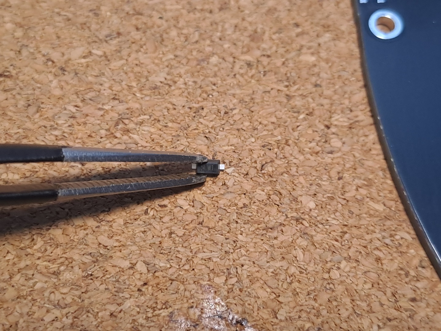
Part Name: Diodes | Quantity: 58
Model / Details: 1N4148W | Brought At: Part of the Kit from Kriscables
Purpose: Manages the flow of electrical current (can only flow in one direction)
Remarks:
-
They also known as “SOD-123”
-
SMD are needed if you want Choc Switches
-
If the PCB you find has Through-hole, then you would need Though-Hole Diodes
Part Name: Microcontroller (Hotswap) Sockets | Quantity: 4x 12
Model / Details: | Brought At: Part of the Kit from Kriscables
Purpose: Allows to easily change (so, no need to solder) the micro controller
Remarks:
-
You need 12 pins per side, per micro controller
-
So 2 Sides x 12 Sockets x 2 Micro Controller
Part Name: Mill Max Socket Pins | Quantity: 4x 12
Model / Details: | Brought At: Part of the Kit from Kriscables
Purpose: The “legs” of the microcontroller, which attach to the HotSwap Sockets
Remarks:
-
Same as the Microcontroller Sockets
- So 2 x 12 x 2
Part Name: TRRS Connector | Quantity: 2
Model / Details: | Brought At: Part of the Kit from Kriscables
Purpose: Connecting the boards together | Remarks:
-
Never disconnect the TRRS cable when the board is connected to the PC
-
Always disconnect the USB first
-
Not necessary if you going for a wireless build
Extras
Part Name: Reset Switch Buttons | Quantity: 2
Model / Details: | Brought At:
Purpose:
Remarks:
Part Name: OLED Displays | Quantity: 2
Model / Details: OLED 128x32mm SSD1306 I2C | Brought At:
Purpose: Seeing Layers, WPM, Battery Status, NumLock / CapsLock State, whatever you want | Remarks:
- Use nice!view v2 if you building wireless, else Battery life will suck
Part Name: Switches | Quantity: 58
Model / Details: MX or Choc Low Profile | Brought At:
Purpose: What registers the “key press”
Remarks:
-
If choosing Choc Low Profile, remember to consider if the “legs” will be able to touch the PCB if you plan on adding Layers in between
-
If you already have a mechanical keyboard, you can always use those switches instead
Part Name: Keycaps | Quantity: 58
Model / Details: MX or Choc Low Profile | Brought At:
Purpose: What your finger presses / what you see when you look at the key
Remarks:
-
MX and Choc Low Profile are not compatible with each other. This also applies to the switches
-
If you already have a mechanical keyboard, you can always use those switches instead
Part Name: USB-C (data + power) cable | Quantity: 1
Model / Details: | Brought At:
Purpose: Connect keyboard to the PC
Remarks:
- If you building wireless, you just need it to flash
Part Name: On / Off Keys | Quantity: 2
Model / Details: | Brought At:
Purpose: Turn the Board On / Off
Remarks:
- This is only needed if you are building Wireless
Part Name: Case | Quantity: 1
Model / Details: | Brought At:
Purpose: Makes everything prettier
Remarks:
- A bottom case is HIGHLY recommended. Rest (top, silencing, middle) are optional
Part Name: Batteries | Quantity: 2
Model / Details: 110mah (3.7v Li-Po 301230) | Brought At:
Purpose: Makes Wireless Keyboard Wireless
Remarks:
-
This is only needed if your are building Wireless
-
Important is that they are 3.7V
Tools
You might already have this laying around if it’s not your first electronic projects. Else you will need:
Part Name: Soldering Iron | Quantity: 1
Model / Details: | Brought At:
Purpose: To solder
Remarks:
Part Name: Tweezers | Quantity: 1
Model / Details: | Brought At:
Purpose: Holding Components in Place & Briding components for testing
Remarks:
Part Name: Solder | Quantity: Some
Model / Details: | Brought At:
Purpose: Like hot glue, but for electronics
Remarks:
- Ideally, Lead Free
Part Name: Solder Wick | Quantity: Some
Model / Details: | Brought At:
Purpose: Fix soldering mistakes
Remarks:
- A Solder Pump is also a nice to have. It’s not an “or” it’s an “and” with Solder Wick
Building & Customization Overview
Building Steps Overview
-
Solder SMD Diodes to the PCB
-
make sure they are aligned correctly
-
this is now your BOTTOM
-
-
Solder Hotswap Sockets of the Microcontroller to the PCB
- on the TOP side
-
Solder the Pins / Legs on the Microcontroller
-
Face down controller on the Hotswap Sockets
-
Legs fully in, solder in an X Pattern
-
-
Flash Basic Firmware
-
Manually bridge each key to make sure they are working
- much easier to find and fix now then later
-
Solder the Key Switches
-
(if using a screen) Solder the Hotswap Sockets for the Display
-
Solder / Bridge the Screen Pins
- even if not using a screen, good idea since no downside from doing it
-
Solder the TRRS / Reset Button
-
(if using RGB) Solder underglow RGB
-
Mount Bottom Plate
-
Mount Middle / Keyswitches Board
-
Add each individual Key Switch
-
Add Top Plate
-
Add Key Caps
-
Repeat for other Keyboard Half
-
Enjoy!
Customizing Steps Overview
-
Make / Adapt Keys, eg using QMK Online Configurator
- Convert your JSON to .c file
-
Make a new Keymap with QMK
-
Paste / Edit your Keymaps .c file
-
Flash your microcontroller
Step by Step Build Guide
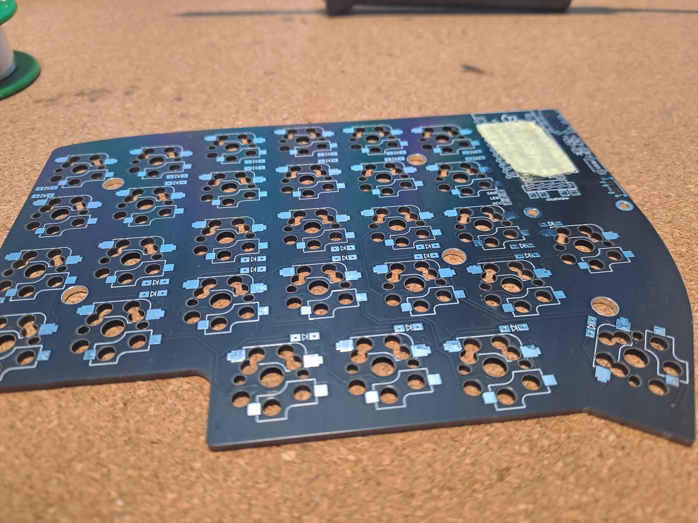
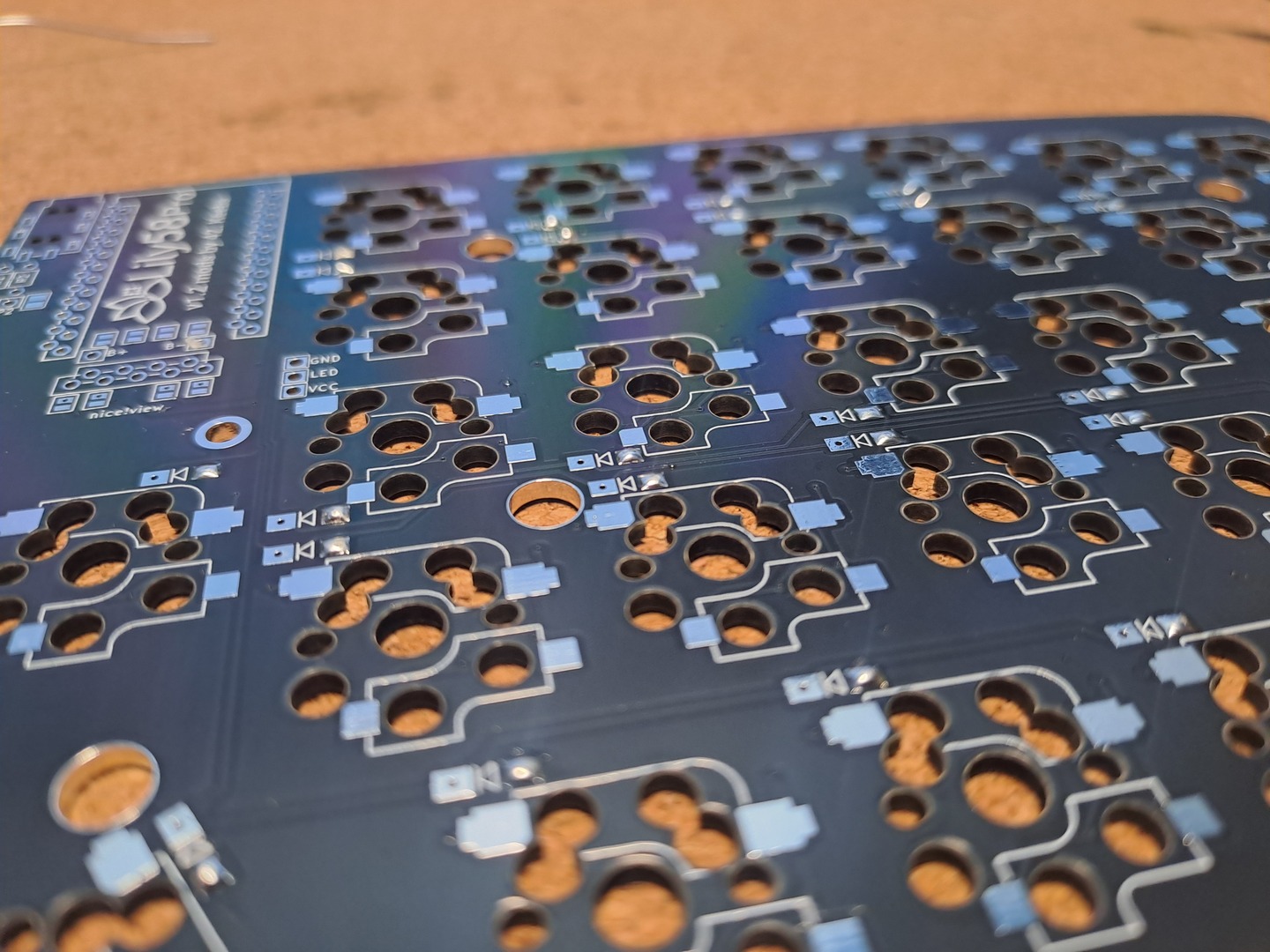
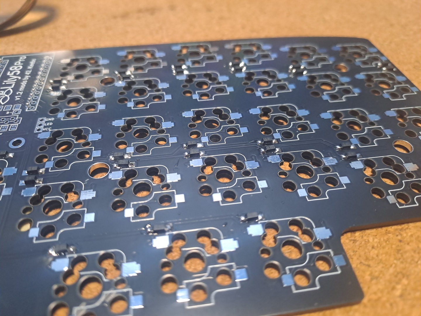
01
Step Overview: Solder the Diodes to to the bottom side of the PCB
Step Details:
-
I recommend using Painter’s Tape or similar and mark the TOP side of the PCB (ask me why)
-
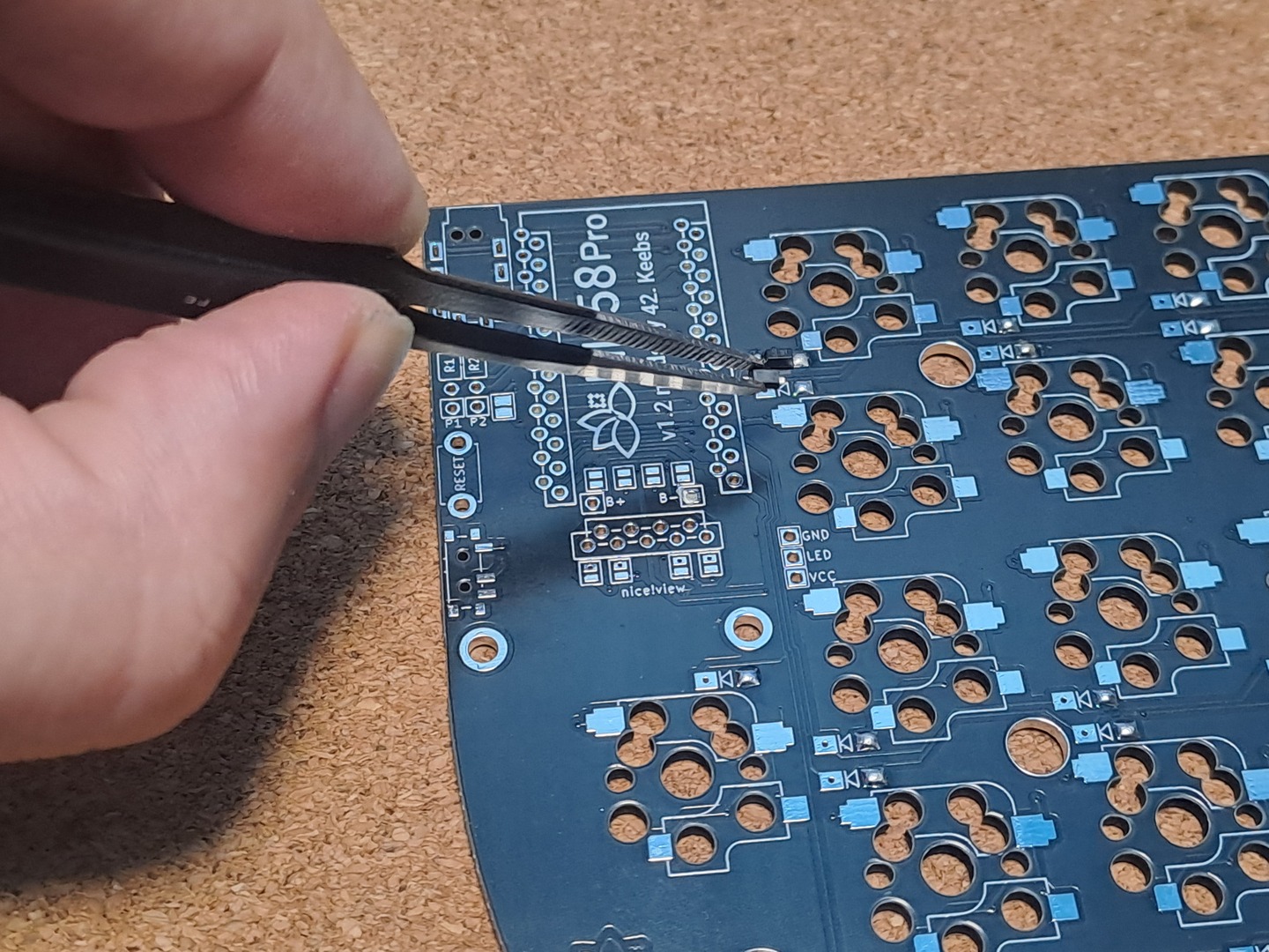
Solder a bit of Solder to one side of the Diode Receiver
-
Using Tweezers, hold the Diode in place, heat the previous solder joint until it falls / push into place
-
Solder the other leg of the Diode
Notes:
Screenshots:
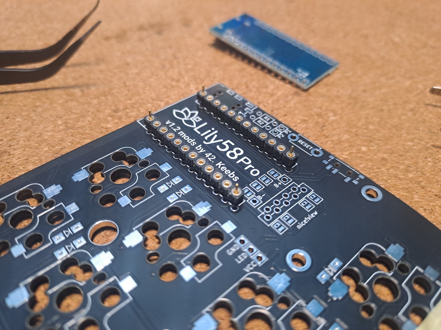
02
Step Overview: Solder the Controller’s Hotswap Sockets
Step Details:
-
Basically it’s the one surronded by a Squared Line
-
Put the Sockets on the TOP side of the PCB
-
Flip the PCB over
-
Solder the legs on each corner
-
Check the Socket is leveled
-
Solder the other legs
Notes:
- You can technically solder the Controller directly to the board, but I HIGHLY recommend against it
- Swapping the controller later, in case it breaks or you want a different one will be a massive PITA.
Screenshots:

03
Step Overview: Solder the Legs of the Microcontroller
Step Details:
-
With the Controller FACING DOWN
-
Put the Mill Max Pins into the sockets. Make sure they are inserted all the way down
-
Solder the Pins
Notes:
Screenshots:
04
Step Overview: Flash the Microcontroller
Step Details:
-
I recommend flashing with the default / a simple firmware / config, so yousure it’s a good / working one
-
To enter flash mode on the ProMicro, just brige GND with RST 2x times
-
If you flashing via CLI, the command is something like:
qmk flash -kb lily58/rev1 -km default
Notes:
Screenshots:
05
Step Overview: Test Each Key
Step Details:
-
It’s much easier to test - and fix - any issue now then later
-
Using Tweezers or your Multimeter, bridge each of the connections
-
Make sure you get one and exactly one key input / signal
-
If a key outputs multiple values:
-
you probably have a solder bridge
-
or a diode is broken
-
-
If a key doesn’t output anything:
-
check your diode, even more they solder joints and orientation
-
maybe the pin on the controller
-
Make sure the key actually have a function you can test - eg: “a” -
-
Notes:
Screenshots:
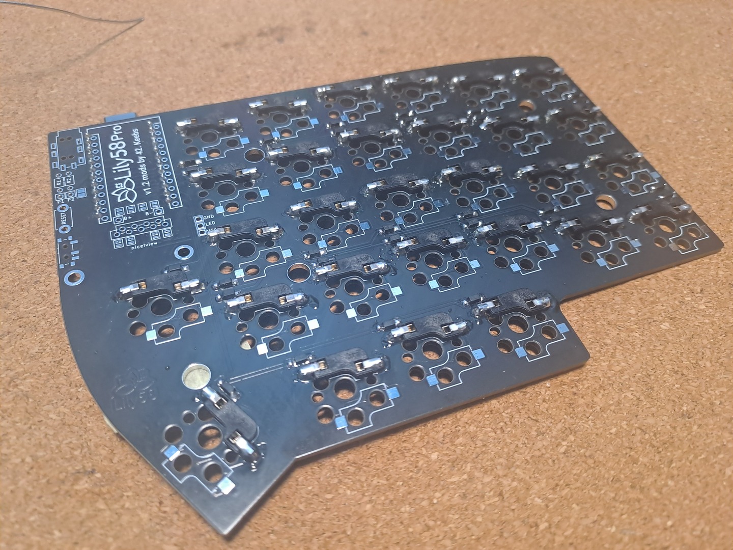
06
Step Overview: Solder the Howswap Switch Sockets
Step Details:
-
On the BOTTOM side of the PCB
-
Remeber that the Socket will go in both ways, but only one way will leave the Hole Available for the Switch
-
Put the Hotswap Socket In
-
Heat up one leg / solder point and apply Solder
-
With your finger on top of it to keep it in place, let it cool down
-
Solder the other “leg”
Notes:
-
While you can technically solder the Switch directly to the PCB, I highly recommend against it
-
It’s very little cost, and unless you are 100% sure you won’t want other switches, ever, it’s worth to add them
-
Repairs are also much easier, since you can just swap the switch instead of having to solder it out
Screenshots:
07
Step Overview: Solder / Bridge the Screen Pins
Step Details:
-
On the TOP side of the PCB
-
Bridge the 4 Jumpers, by soldering them 2 by 2 Vertically
-
Even if you don’t plan on using the OLED Screens, still recommended, since there is no harm in having them bridged
Notes:
Screenshots:
08
Step Overview: Solder the TRRS / Reset Button / OLED Hotswap Socket
Step Details:
-
Solder the TRRS
-
Solder the Reset Button
-
If using a Screen, Solder in the Hotswap Socket
Notes:
Screenshots:
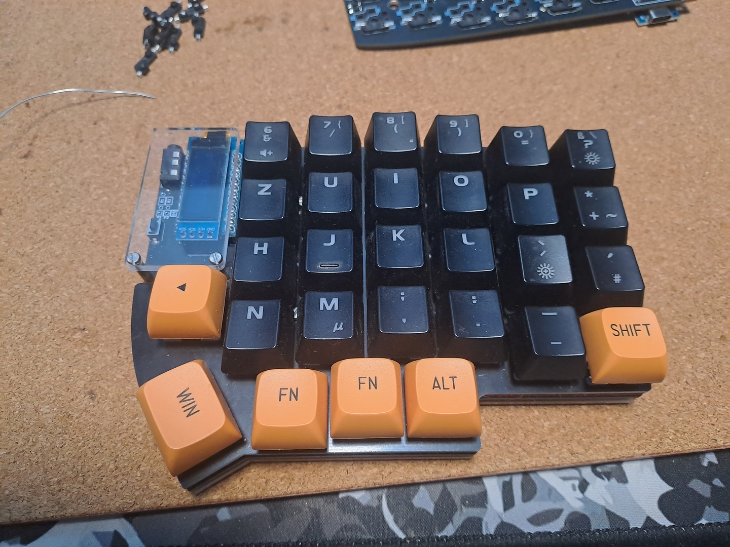
09
Step Overview: Final Test Pre-Assembly
Step Details:
-
Now it’s a good point to put the Screen on and Check it everything works
-
Bridging / Activating the Switches should also be working as expected
Notes:
Screenshots:
10
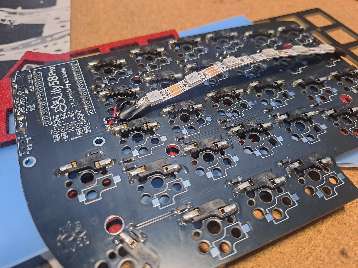
Step Overview: Solder the Underglow RGB
Step Details:
-
By far the most challenging solder, mainly on the dables
-
Remember the Cable will go on the BOTTOM side
-
Solder the 5V, Signal and GND with Cables
-
Solder the cables to the holes in the PCB
-
Remember that you can either solder the cables in the same direction or both pointing from in > outwards
Notes:
Screenshots:
11
Step Overview: Assemble the Case
Step Details:
-
Add Screws and Raisers to the Bottom Layer
-
Add OLED Cover Screws and Raisers to PCB Layer
-
PCB Layer on Top of Bottom Layer
-
Dampening Layer
-
Top Layer
-
Everything Still Working?
-
Switches
-
OLED Covers
-
Keycaps
Notes:
If you have less layers, just skip the ones you don’t have
Screenshots:
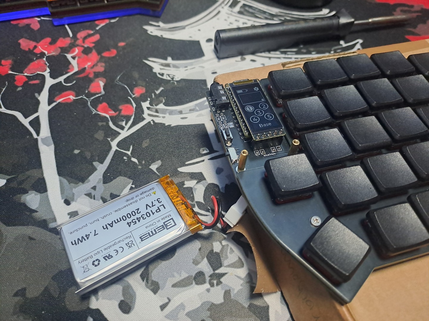
12
Step Overview: If building Wireless, Battery time
Step Details:
-
Solder the On / Off Switch to the board
-
Solder the JST Plug to the Board
-
Connect the Battery
Notes:
-
A JST Plug - or similar - is *HIGHLY* recommended.
-
If you want a bigger battery (like the one on the photo), you need to get a “custom” bottom, so it can house the battery.
-
If you want something that fits between Board and PCB the biggest you can probably fit is a 301230 LiPo
-
ProTip: those numbers are the size of the battery. Just make sure you using a 3.7v one.
Screenshots:
References / Sources
Kriscables Lily58 Written Build Guide
Kriscables Lily58 YouTube Video
Splitkb Aurora Series Written Build Guide